In this article
- What an industrial electrical installation covers
- LV panels: what to specify and check
- Cabling: selection, routing and installation
- Testing an industrial electrical installation before energising
- Maintenance and periodic inspection
- Regulatory context in Nigeria
- Common mistakes to avoid
- FAQ
- Talk to Maven about your electrical installation
An industrial electrical installation is the part of a factory that nobody notices until it fails. When it is done well, power reaches every motor, heater and control panel safely and without fuss. When it is done badly, you get nuisance tripping, hot joints, burnt cable trays and, in the worst cases, fires and electric shock. This guide walks through the three areas that decide whether an industrial electrical installation is sound: the low-voltage (LV) panels, the cabling, and the testing that proves the work before it is energised.
It is written for plant managers and project owners. It is not a design manual; it explains what good practice looks like and what to ask your contractor.
What an industrial electrical installation covers
In a typical Nigerian factory, the electrical installation starts at the point of supply, whether that is a utility transformer, a private substation or a bank of generators, and ends at the terminals of each piece of equipment. Between those points sit several layers:
- Main LV switchboard receiving power from the transformer and generators, often through a changeover arrangement.
- Sub-distribution boards serving each production area, utility block or building.
- Motor control centres (MCCs) housing starters, variable speed drives and their protection.
- Power and control cabling on trays, ladders, trunking or in ducts.
- Final circuits for lighting, small power, welding outlets and instrumentation supplies.
- Earthing and bonding tying the whole system together for safety.
Because many plants run on a mix of grid power and diesel or gas generators, the main board often has to handle two or more sources. The changeover scheme, interlocks and generator synchronising (where used) need to be designed alongside the board, not added later.
LV panels: what to specify and check
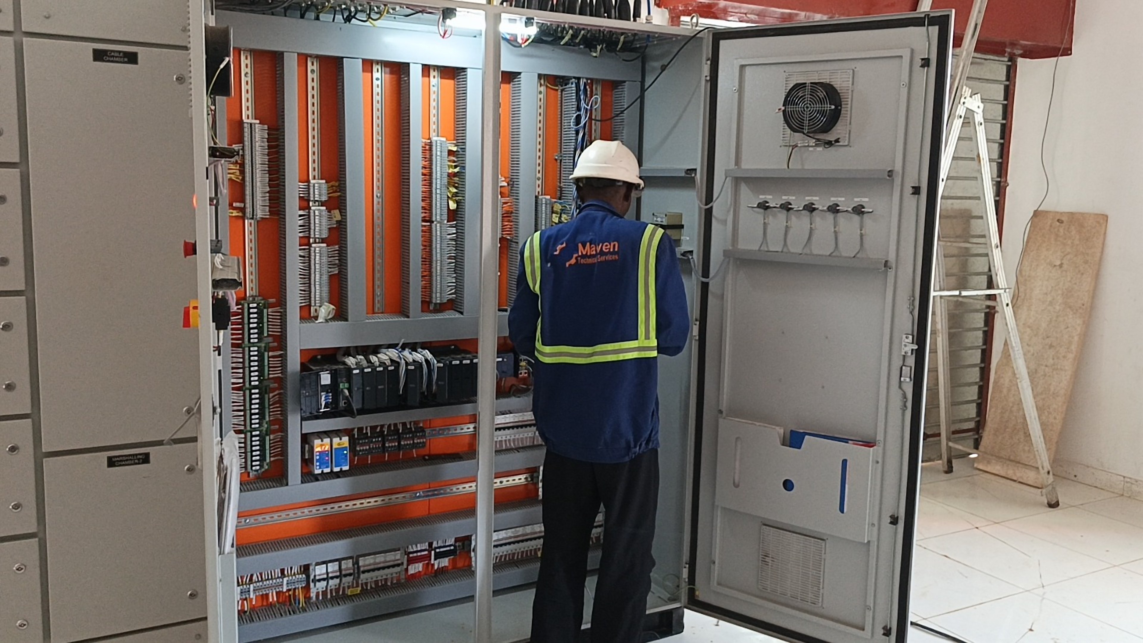
LV switchboards and MCCs are the heart of the installation. The main international standard for them is IEC 61439. Part 1 sets the general rules, and Part 2 covers power switchgear and controlgear assemblies. ABB’s technical guide to the standard notes that Part 1 cannot be used on its own to specify an assembly; a power board is declared against Part 2.
Design verification and routine verification
IEC 61439 splits responsibility between two parties. The original manufacturer designs the panel system and carries out design verification: proving things such as temperature rise, short-circuit withstand, dielectric properties, clearances and creepage distances, degree of protection and mechanical operation. This can be done by testing, by comparison with a tested reference design, or by assessment, depending on the characteristic.
The assembly manufacturer, the panel builder whose name is on the nameplate, then builds each board to the original manufacturer’s instructions and carries out routine verification on every unit. That covers degree of protection, clearances, protection against electric shock, installation of components, internal wiring, terminals, mechanical operation, dielectric tests and a functional check of wiring and operation.
When you buy a board, ask for both: evidence that the panel system has been design-verified, and a routine verification record for your specific panel.
Forms of separation
IEC 61439 describes internal separation from Form 1 (no internal segregation) to Form 4 (busbars, functional units and terminals separated from each other). Higher forms make it safer and easier to work on one outgoing circuit while others stay live, which matters in a plant that cannot shut down the whole board for every modification. They also cost more and take more space, so the choice should follow how the board will actually be operated and maintained.
Panel specification checklist
| Item | What to confirm |
|---|---|
| Rated current | Busbar and incomer ratings with allowance for future load |
| Short-circuit rating | Matched to the prospective fault level at the board, from transformer and generators |
| Form of separation | Agreed with operations and maintenance teams |
| Degree of protection (IP) | Suited to dust, moisture and washdown in the area |
| Ambient temperature | Derating for hot switchrooms; ventilation or air-conditioning if needed |
| Changeover and interlocks | Grid/generator transfer scheme, mechanical and electrical interlocks |
| Metering and monitoring | Energy meters, power quality analysers, links to SCADA if required |
| Spare capacity | Spare ways and space for future outgoing circuits |
Switchroom layout
A good panel in a poor room is still a problem. Leave enough clear space in front of and behind boards for doors to open fully and for safe withdrawal of breakers. Keep water pipes and drains out of switchrooms. Provide two exits from large rooms, adequate lighting, and a way to keep dust out. In much of Nigeria, harmattan dust and high humidity both shorten the life of switchgear, so sealed cable entries, filtered ventilation and regular cleaning are worth planning in from the start.
Cabling: selection, routing and installation
Cable work makes up a large share of any industrial electrical installation, and it is where shortcuts are most often taken. The aim is simple: every cable should carry its load without overheating, keep voltage drop within limits, survive a fault until protection operates, and be installed so it is not damaged.
Sizing cables
Cable sizing is usually carried out to IEC 60364 or, where British practice is followed, BS 7671. The designer considers:
- Current-carrying capacity, corrected for ambient temperature, grouping with other cables and installation method.
- Voltage drop from the origin to the load.
- Fault withstand, so the cable survives a short circuit until the protective device clears it.
- Disconnection times, so earth faults are cleared quickly enough to prevent dangerous touch voltages.
For voltage drop, BS 7671 Appendix 4 gives commonly used limits. For an installation supplied directly from a public LV network, the limits are 3% for lighting and 5% for other uses. For an installation supplied from a private LV supply, the figures are 6% for lighting and 8% for other uses. Long runs to remote pump houses, water treatment plants or tank farms are where these limits bite, and where an undersized cable shows up as motors that struggle to start.
Routing and support
- Use cable ladders for heavy power cables and perforated trays for lighter runs. Size them with room to spare.
- Segregate power cables from instrument and data cables to limit interference, and follow the drive manufacturer’s guidance for VSD motor cables.
- Keep cables away from steam lines, boiler flues and other hot surfaces.
- Protect cables where they pass through walls and floors, and seal fire-rated penetrations.
- Respect minimum bending radii given by the cable manufacturer, especially for armoured and large cables.
- Label both ends of every cable with an identifier that matches the cable schedule.
Terminations
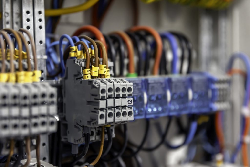
Many electrical faults start at a poorly made joint. Use the correct lug and crimping tool for each conductor size, tighten terminals to the manufacturer’s torque, and terminate armour and glands properly so they provide earth continuity where the design relies on them. A loose termination may work for months before it overheats.
Testing an industrial electrical installation before energising
No installation should be switched on until it has been inspected and tested. In IEC terms this is the initial verification described in IEC 60364-6; in British practice it follows BS 7671 Part 6. The tests are done in a set order, with the installation dead for most of them.
Visual inspection
Before any instrument comes out, check that the installation matches the drawings, that the right equipment has been fitted, that cables are supported and labelled, that barriers and covers are in place, and that there is no visible damage. Many problems are caught at this stage.
Dead tests
- Continuity of protective conductors, including main and supplementary bonding.
- Continuity of ring final circuits where these are used.
- Insulation resistance between live conductors and between live conductors and earth.
- Polarity, confirming switches and protective devices are in the line conductor.
- Earth electrode resistance where the installation has its own electrodes.
Insulation resistance test voltages and minimum values in BS 7671 are summarised below. Readings well above the minimum are expected on new work; a reading close to the limit should be investigated even if it technically passes.
| Circuit nominal voltage | Test voltage (d.c.) | Minimum insulation resistance |
|---|---|---|
| SELV and PELV (extra-low voltage) | 250 V | 0.5 MΩ |
| Up to and including 500 V (e.g. 230/400 V) | 500 V | 1 MΩ |
| Above 500 V | 1000 V | 1 MΩ |
Disconnect or protect sensitive electronics such as drives, PLCs and surge protective devices before insulation testing, as the test voltage can damage them or give false readings.
Live tests
- Earth fault loop impedance, to confirm protective devices will disconnect in the required time.
- Prospective fault current at each board, checked against equipment ratings.
- RCD operation where residual current devices are fitted.
- Phase rotation, before any motor is coupled to its load.
- Functional tests of interlocks, changeover schemes, emergency stops and control circuits.
Documentation
Testing is only useful if it is recorded. At handover you should receive an installation certificate, schedules of test results for every circuit, as-built single line diagrams, cable schedules, panel routine verification records and protection settings. Keep them; they become the baseline for every future inspection.
Maintenance and periodic inspection
An installation that passed its tests on day one will not stay perfect. Vibration loosens terminals, dust builds up in panels, and loads grow as new machines are added. A sensible regime includes:
- Periodic inspection and testing at intervals set by a competent person, based on the environment and use.
- Thermographic (infrared) surveys of panels under load to find hot joints before they fail. In the United States, NFPA 70B, which became a standard in its 2023 edition, calls for annual infrared inspections of electrical equipment; it is a useful benchmark even where it is not law.
- Cleaning and re-torquing of terminations during planned shutdowns.
- Checking protection settings after any change to the supply, such as a new generator or transformer.
- Updating drawings whenever circuits are added or changed.
Regulatory context in Nigeria
In Nigeria, the Nigerian Electricity Management Services Agency (NEMSA) is responsible for the technical inspection, testing and certification of electrical installations and for enforcing technical standards in the power sector. Owners planning substations, transformers or large new installations should factor NEMSA inspection and certification into the project timeline, alongside the client’s own insurance and corporate safety requirements.
Common mistakes to avoid
- Buying panels on price alone without evidence of IEC 61439 verification.
- Ignoring generator fault levels and changeover arrangements when rating switchgear.
- Undersizing long cable runs and suffering excessive voltage drop.
- Mixing power and instrument cables in the same tray without segregation.
- Skipping insulation resistance testing because the cable is new.
- Energising without signed test records.
- Failing to update drawings, so the next team works from wrong information.
FAQ
What is the difference between design verification and routine verification?
Design verification proves that a panel design meets IEC 61439, and is the original manufacturer’s job. Routine verification is carried out on each individual panel by the builder to show it has been assembled correctly.
Which form of separation should I choose?
It depends on how much work you expect to do on the board while it is live and how critical continuity of supply is. Many industrial MCCs use a higher form so that individual feeders can be worked on safely. Discuss it with your operations and maintenance teams before ordering.
Why test insulation resistance on new cable?
Cables can be damaged during pulling, by sharp tray edges or by poor terminations. An insulation resistance test finds these faults before the cable is energised.
How often should a factory installation be inspected?
There is no single interval for every site. It should be set by a competent person based on the environment, the type of use and the condition found at the last inspection, with thermographic surveys in between.
Talk to Maven about your electrical installation
Maven Technical Services designs, installs and tests industrial electrical systems alongside the steel structures, piping and utilities that make up a working plant. If you are planning new switchboards, a cable replacement or an extension to your factory’s power distribution, speak to Maven’s engineers about the scope, the testing and the documentation you should expect.