In this article
- What is in a motor control centre?
- Specification before MCC panel installation
- Preparing the switchroom
- Receiving, storage and handling
- Setting and joining the sections
- Cabling and terminations
- Testing before energisation
- Handover documentation
- Common mistakes to avoid
- FAQ
- Talk to Maven about your MCC project
A motor control centre (MCC) is where a factory’s motors are started, stopped, protected and controlled. Pumps, fans, conveyors, mixers and compressors all depend on it. Good MCC panel installation is what turns a well-built panel from the factory floor into a reliable piece of plant. Rushed installation, with loose busbar joints, poor cable terminations or skipped tests, leads to hot spots, nuisance trips and failures that stop production.
This guide walks through the life of an MCC project on site: what to specify, how to prepare the switchroom, how to receive and set the panel, how to make the connections, and the tests that must be completed before it is energised. It is written for plant managers, project engineers and maintenance teams.
What is in a motor control centre?
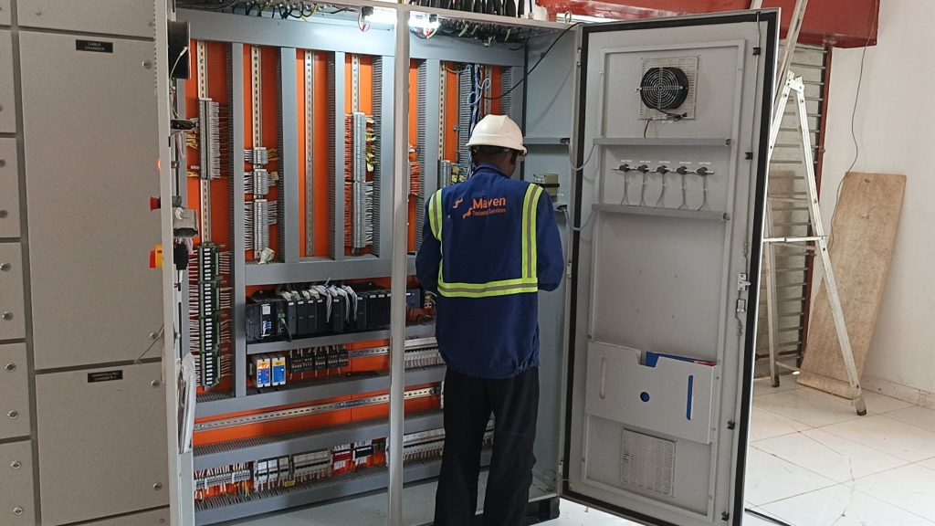
An MCC is a low-voltage assembly made up of vertical sections that share a common horizontal busbar. Each section holds a number of functional units, sometimes called buckets or drawers, and each unit typically controls one motor. A unit might contain:
- A circuit breaker or fuse switch for short-circuit protection.
- A contactor, soft starter or variable speed drive.
- An overload relay or electronic motor protection relay.
- Control circuit components, indicators and terminals.
- Communication modules where the MCC is linked to a PLC or SCADA system.
Fixed, plug-in and withdrawable units
Units can be fixed (bolted and wired in place), plug-in (connected to the busbar by stabs but with outgoing wiring fixed) or withdrawable (racked in and out, with power and control connections made automatically). Withdrawable designs cost more but let a faulty starter be swapped quickly, which matters on continuous process lines. Some manufacturers, such as Mitsubishi Electric, describe withdrawable units with automatic connection of both main and control circuits.
Specification before MCC panel installation
An MCC should be specified to the low-voltage assembly standard IEC 61439, Parts 1 and 2. Manufacturers state compliance in their literature; ask for evidence of design verification for the panel system and routine verification records for your specific panel.
| Item | What to decide |
|---|---|
| Busbar rating | Horizontal and vertical busbar current with allowance for future motors |
| Short-circuit withstand | Matched to prospective fault level from transformer and generators |
| Form of separation | Higher forms, such as Form 4b, separate units and terminals so one feeder can be worked on while others stay live |
| Unit type | Fixed, plug-in or withdrawable |
| Starter types | Direct-on-line, star-delta, soft starter or VSD, per motor |
| Degree of protection | IP rating suited to dust and moisture in the switchroom |
| Internal arc | Whether internal arc testing to IEC TR 61641 is required |
| Controls and communication | Hard-wired, fieldbus or Ethernet; interface with PLC/SCADA |
| Spare capacity | Spare equipped units and empty spaces for future motors |
Think about heat and dust
Variable speed drives and soft starters generate heat. Many Nigerian switchrooms are hot, and harmattan dust adds to the problem. The panel’s rating assumes a stated ambient temperature, so confirm what that is and whether the room needs ventilation or air-conditioning. Specify filtered ventilation or sealed designs for dusty locations.
Preparing the switchroom
The room should be ready before the MCC arrives. ABB’s installation manual for one of its MCC ranges sets out several requirements that apply broadly:
- A level floor. ABB specifies the floor should be straight and level within a tight tolerance over the full length and depth of the line-up. An uneven floor twists the frames and makes busbar alignment and door operation difficult.
- Cable entries in place. Conduits, trenches or floor openings should be installed before the panel is moved in, with openings covered until use.
- Clearances. Leave the manufacturer’s required space above, behind and in front of the panel, plus any space for arc venting.
- Fixings. Bolt the panel to the floor as shown on the manufacturer’s drawings. ABB does not recommend welding.
- Environment. No water pipes overhead, adequate lighting and a means of keeping dust out.
Receiving, storage and handling
Damage in transit and poor storage cause more problems than people expect.
- Inspect on arrival. Check for damage and compare the contents with the packing list before discarding packing. Report problems to the carrier and supplier immediately.
- Store indoors. ABB recommends dry, well-ventilated indoor storage on a paved floor, with a moisture barrier over the equipment. Where the panel has anti-condensation heaters, energise them during long storage in humid conditions.
- Handle with care. Use the lifting points and methods in the manual (forklift, crane with spreader bar, or rollers). Keep doors secured. Remove shipping bases only once the sections are in position.
Lagos humidity can lead to condensation inside a panel stored in a container or open shed for weeks. If storage is unavoidable, keep it dry and check for moisture before installation.
Setting and joining the sections
Larger MCCs arrive in shipping sections that are joined on site.
- Position the sections, level them and bolt them together and to the floor.
- Make the busbar splices carefully. Clean contact surfaces as the manufacturer instructs without removing plating, use the supplied hardware, and tighten to the specified torque. Record torque values.
- Reconnect control wiring across the shipping splits using the connection diagram.
- Connect the earth bar between sections and to the site earthing system using a conductor of at least equal size.
Busbar joints are the single most important site connection. A joint that is not clean, flat and correctly torqued will run hot and may eventually fail.
Cabling and terminations
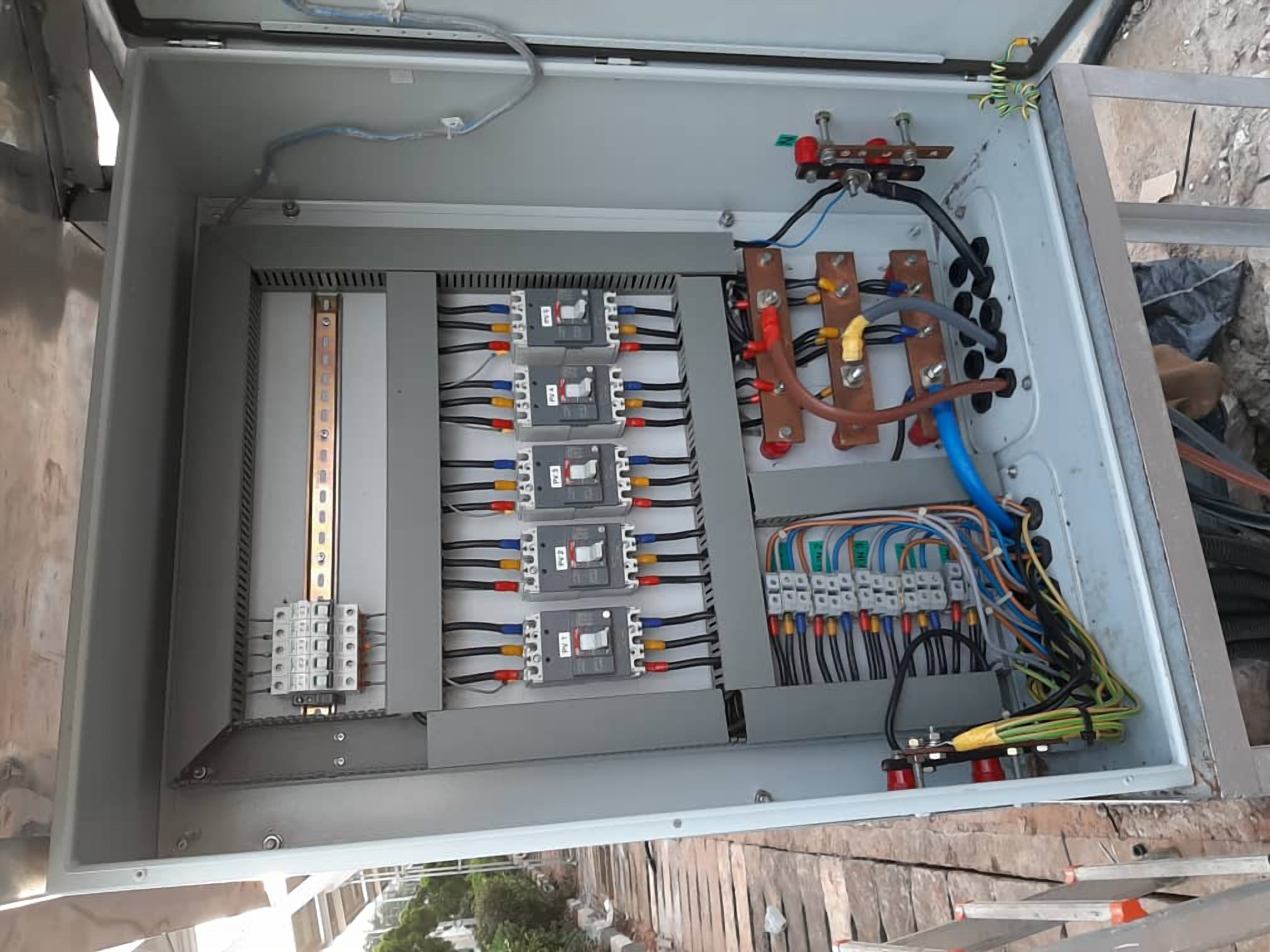
- Bring cables in through the gland plates shown on the general arrangement drawings, with the correct glands to maintain the IP rating and, where relevant, arc-resistant performance.
- Segregate power, control and instrument cables, both inside the panel and on cable trays.
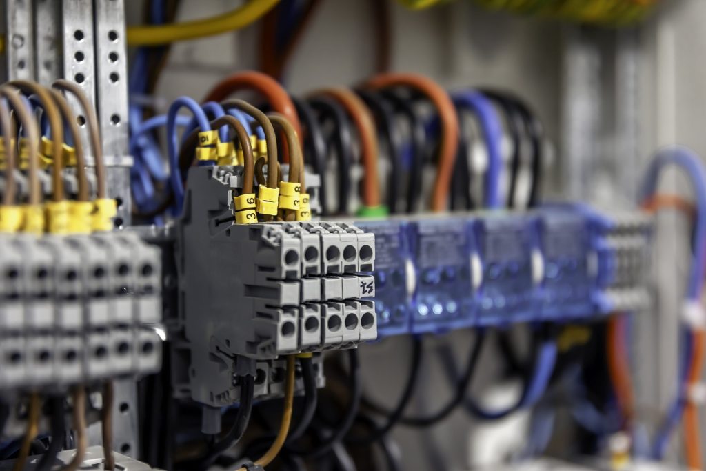
- Use correctly sized lugs and crimping tools, and tighten terminals to the specified torque.
- Support cables so their weight does not hang on terminals.
- Label every cable and core to match the drawings.
- Seal unused entries against vermin and dust.
- For VSD outputs, follow the drive manufacturer’s guidance on screened cables and earthing to control interference.
Testing before energisation
Never energise an MCC on the strength of a visual check. The test programme should be written down and the results recorded. A typical sequence:
Mechanical and visual checks
- Remove all packing, shipping blocks and foreign objects.
- Confirm internals are clean and dry.
- Check torque marks on busbar joints and main terminations.
- Check the mechanical operation of breakers, switches, interlocks and withdrawable units.
- Confirm earthing connections and protective conductor continuity.
Electrical tests
- Insulation resistance of busbars and outgoing circuits, with sensitive electronics disconnected as the manufacturer instructs.
- Dielectric (high-voltage) testing where specified, using the manufacturer’s field test values and never exceeding the equipment rating.
- Continuity of power and control circuits.
- Protection settings entered and checked for each motor: overload, short-circuit, earth fault. ABB notes that protective devices are often not set at the factory.
- Control circuit function tested using a temporary control supply with main power isolated: start, stop, interlocks, emergency stops and indications.
- Phase rotation checked at the incoming supply.
Energising and motor runs
ABB’s manual sets out a staged energising sequence: confirm all doors are closed and units are disconnected, energise the incoming supply, check instruments, close the main breaker to energise the busbar, then connect and operate individual units. For each motor, carry out an uncoupled bump test to confirm rotation, then a coupled run while recording current against nameplate values.
Thermographic survey
Once the MCC has run under load, a thermal imaging survey quickly finds any joints or terminations running hotter than their neighbours.
Handover documentation
- As-built single-line diagrams, schematics and general arrangement drawings.
- Routine verification report from the panel builder.
- Site test records: insulation resistance, continuity, torque, protection settings and functional tests.
- Motor run records.
- Manufacturer’s manuals and spare parts list.
Maintenance
ABB’s manual includes periodic checks of bolted connections, control wiring, filters, heaters and indicators. Most plants combine these with annual thermography and checks at planned shutdowns.
Regulatory note
The Nigerian Electricity Management Services Agency (NEMSA) has a statutory role in the inspection, testing and certification of electrical installations and equipment. Larger projects should allow for NEMSA requirements alongside insurer and corporate standards.
Common mistakes to avoid
- Delivering the MCC before the switchroom floor, cable trenches and roof are finished.
- Storing the panel for weeks in a container or open shed without heaters or moisture protection.
- Tightening busbar splices by feel rather than to the specified torque, and not recording it.
- Leaving gland plates unsealed, letting dust and vermin into the panel.
- Assuming protection relays and overloads were set at the factory.
- Running motors coupled to their loads before rotation has been checked.
- Handing over without updated drawings, so the first fault-finding job starts with wrong information.
FAQ
Should we choose withdrawable or fixed units?
Withdrawable units cost more but allow quick replacement of a faulty starter, which suits critical continuous processes. Fixed units are adequate where downtime for repair is acceptable.
What form of separation does an MCC need?
It depends on how often units will be worked on while the rest of the MCC is live. Many industrial MCCs use Form 4 arrangements for this reason. Agree it with operations and maintenance.
Why test insulation resistance on a new panel?
Transport, storage and site work can damage insulation or let moisture in. An insulation resistance test finds problems before the panel is energised.
Can VSDs go in the same MCC as DOL starters?
Yes, and many MCCs mix starter types. Allow for the extra heat from drives and follow cabling and earthing guidance to control interference.
Talk to Maven about your MCC project
Maven Technical Services installs and tests industrial electrical systems, including switchboards, motor control centres and the cabling between them. If you are planning a new MCC, extending an existing one or replacing an ageing board, speak to Maven’s engineers about installation, testing and the documentation you should receive at handover.